Views: 0 Author: Site Editor Publish Time: 2026-05-28 Origin: Site
Think of cardboard tube cutting not as a simple mechanical step, but as a critical quality checkpoint. Inconsistent cuts, edge burrs, or crushed cores directly cause costly downstream failures. These defects trigger misalignment during automated film winding. Excess paper dust creates false sensor readings. Jagged edges lead to severe adhesive contamination. You cannot afford these disruptions.
As production scales rapidly, manual or semi-automatic methods fail. They simply cannot deliver the speed, safety, and strict tolerances required by modern packaging and converting lines. Operators experience fatigue, and precision drops significantly over a long shift. You need a highly reliable system to protect your entire manufacturing output.
This guide breaks down the core mechanical principles behind automated equipment. We will explore the standard operational workflow you should implement on your factory floor. Finally, we provide the strict evaluation criteria you must use when sourcing an Automatic Carboard Tube Cutter for high-volume production.
Precision Mechanics: Modern cutters rely on servo-driven positioning and high-speed rotary scoring wheels rather than brute-force pressing, ensuring clean edges without crushing the tube.
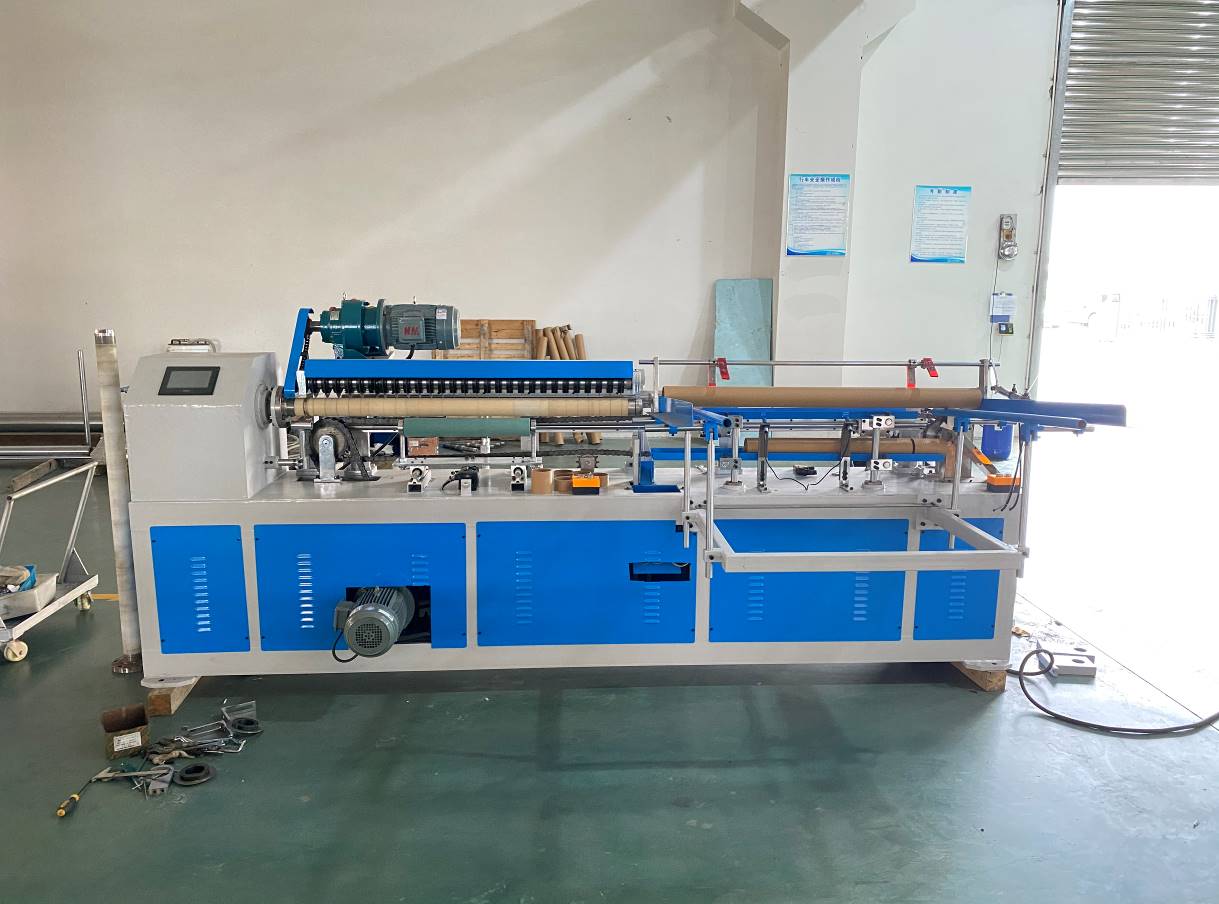
Modular Systems: The equipment operates across four synchronized subsystems: Feeding, Cutting, PLC/HMI Control, and Discharging.
Standardized SOP: Automated workflows reduce operator dependency to simple HMI setups, material loading, and routine safety checks.
Sourcing Reality: Choosing a reliable Automatic Carboard Tube Cutter manufacturer requires vetting their PLC component origins, structural rigidity, and willingness to run custom material tests (proofing) before purchase.
To understand why modern equipment outperforms older machinery, we must examine the physics of the cut. An industrial Automatic Carboard Tube Cutter utilizes a highly refined slicing action. It does not rely on brute force.
The system depends on the physical interaction between a high-speed rotating scoring wheel and the paper mandrel. In some models, a circular saw blade replaces the scoring wheel. The cutting tool makes contact while the paper tube counter-rotates. The blade slices through the kraft paper layers sequentially. This continuous rotary friction prevents tearing. Older mechanical punch systems force a blade straight down. That sheer pressure inevitably distorts the tube shape. Rotary scoring protects the structural integrity of the core.
Precision requires flawless communication between software and hardware. The machine uses advanced servo logic. Control cards generate rapid pulse signals. They send these pulses directly to the servo drives. This process translates digital length inputs from the touchscreen into exact mechanical positioning. A standard AC motor stops based on rough timing. A servo motor stops based on exact encoder feedback. This closed-loop system prevents micro-deviations. Every cut matches the targeted dimension perfectly.
This specific cutting principle generates immediate quality improvements. It directly prevents tube crushing. Rotary action eliminates jagged, frayed edges. Clean edges ensure smooth unwinding for end-users. Furthermore, the scoring method drastically reduces paper dust generation. Clean-room environments and high-precision packaging facilities demand low-dust operations. Airborne paper particles ruin sensors and contaminate adhesives. Minimizing waste at the cutting stage protects your entire production line.
Cutting Mechanism | Edge Quality | Dust Generation | Core Deformation Risk |
|---|---|---|---|
Rotary Scoring (Servo-Driven) | Smooth, clean cut | Extremely low | None |
Brute-Force Pressing (Pneumatic) | Frayed, uneven | Moderate to High | High (Crushing occurs) |
Manual Sawing | Jagged, inconsistent | Very High | Moderate (Operator dependent) |
Industrial cutting equipment functions as a synchronized unit. It integrates multiple specialized components. We can divide the machine into four distinct sub-systems. Each plays a vital role in continuous operation.
Continuous production requires seamless material handling. The feeding system eliminates manual lifting and loading during the operational cycle. Facilities typically load master cores into a V-hopper. Gravity and mechanical agitation align the tubes. Heavy-duty conveyor belts pull the material forward. Pneumatic pushers then index the tube into the cutting chamber. Sensors detect the material presence. They signal the pusher to advance or retract. This synchronized movement ensures continuous feeding without operator intervention.
The cutting system handles the actual physical separation. It requires massive rigidity. The clamping mechanics utilize specialized chucks or expanding mandrels. These devices lock inside the tube. They stabilize the core entirely. Stabilization prevents chatter and vibration during the cut. The adjustable blade housing sits above or beside the mandrel. Operators or automated servos control the penetration depth. Exact depth control ensures the blade cuts through the paper wall without violently striking the metal mandrel beneath.
Consider this the "brain" of the machine. The Programmable Logic Controller (PLC) handles all timing, speed, and safety logic. Operators interact through the Human-Machine Interface (HMI). Intuitive touchscreens simplify complex tasks. Operators use the HMI to set batch quantities. They input desired cut lengths. The screen displays real-time sensor feedback. It flags error codes immediately. An industrial-grade PLC ensures high uptime and reliable troubleshooting data.
Once the blade separates the material, the discharging system takes over. Finished cores safely eject via angled chutes. High-speed models use synchronized exit conveyors. The system must separate usable finished products from waste trim. Some machines feature automated sorting gates. A quick pneumatic blast or mechanical kicker removes the uneven end-pieces. Only perfect cores reach the final collection bin.
Automated equipment delivers high efficiency only when paired with strict operational discipline. You must establish a rigid Standard Operation Process (SOP). This reduces operator dependency. It standardizes daily output. Follow these four phases.
Operators must begin every shift with physical inspections. Do not skip this phase.
Verify stable pneumatic pressure at the main regulator. Inadequate air pressure causes clamping failure.
Check all main electrical connections and emergency stop buttons.
Inspect the V-hopper and cutting platform. You must clear all paper debris, dust, and trim from previous shifts.
Apply lubrication to designated linear guides according to the maintenance schedule.
Next, configure the machine for the specific production run.
Adjust the feeding platform for the exact master tube diameter.
Install the correct internal mandrel. Lock it securely in place.
Inspect the cutting blade. Secure the blade housing and adjust the depth limiters.
Power on the HMI. Navigate to the job screen. Input the target length, total batch quantity, and desired cycle speed.
Never start a full batch blindly. You must validate the setup.
Load five to ten master cores into the automated feeding hopper.
Engage the automated feeding mechanism slowly. Watch the material enter the clamping zone.
Perform a single-cycle test cut in manual mode.
Remove the cut sample. Measure it with digital calipers. Verify the cut tolerance. Inspect the edge smoothness for any burrs.
Adjust the HMI length offset or blade depth if necessary.
Transition to fully automated production once you verify the trial cut.
Switch the PLC to automatic mode. The machine will feed, cut, and discharge continuously.
Monitor the initial 50 cuts. Listen for abnormal vibrations or grinding noises.
Once the batch completes, transition to shutdown procedures.
Reset all panel data for the next shift.
Engage mechanical safety lockouts. Perform end-of-shift vacuum cleaning to remove paper dust from the sensors.
Even premium automated systems encounter mechanical drift. Material variations cause unpredictable results. We draw on deep operational experience to address realistic production issues. You must recognize these failures early.
Frayed edges ruin the visual appeal of packaging. They also interfere with downstream automation. Dull blades represent the most common culprit. Kraft paper contains abrasive recycled fibers. These fibers dull high-speed steel quickly. Incorrect feed pressure also causes burrs. If the blade pushes too hard, it tears the final layer instead of slicing it. Slippage on the mandrel creates a tearing action as well.
Solution: Upgrade to heavier-duty clamping mechanisms. Switch to tungsten carbide blades for abrasive paper. Establish strict, data-driven blade replacement schedules based on linear meters cut, not simply weeks in operation.
Packaging machines require exact core lengths. Variations cause rolls to jam in cartons. Length inconsistencies typically result from encoder drift. Dust accumulation on the optical encoder wheel causes missed pulses. Loose mechanical fixtures also cause the indexing carriage to over-travel.
Solution: Implement routine calibration of the servo system. Check the coupling between the servo motor and the ball screw. Perform daily mechanical retightening of the linear rail carriage. Blow out the encoder housing with dry compressed air weekly.
A crushed tube becomes instant waste. This failure occurs when clamping pressure exceeds the structural limits of the paper wall. It also happens when the mandrel size mismatches the tube's internal diameter. A loose mandrel allows the tube to collapse inward under the blade's downward pressure.
Solution: Reduce the pneumatic pressure on the external chucks. Always use the exact matching mandrel for your specific internal diameter. Never attempt to cut a 3-inch core on a 2.9-inch mandrel. The gap invites structural failure.
Purchasing capital equipment involves significant risk. You must evaluate the vendor as rigorously as the machine itself. Use this checklist to filter out unreliable suppliers. Communicate these points clearly to your Automatic Carboard Tube Cutter manufacturer before requesting a quote.
Never ask a vendor for a "standard machine." Document your exact production realities first. You must define the internal diameter (ID) range. Record your minimum and maximum wall thickness. Specify the maximum master length you intend to load. Finally, calculate your required daily output volume in pieces per hour. Providing this data prevents vendors from undersizing the motors.
Assess your operational model to determine the correct automation level. Do you run a multi-shift, high-volume operation with a fixed SKU? If yes, a fully automatic system yields the best payback period. It replaces three manual operators. Do you run a lower volume, high SKU mix operation? A semi-automatic model might serve you better. Quick changeovers matter more than continuous speed in high-mix environments. Calculate the labor savings to justify the capital expenditure.
Poor quality electronics fail quickly. Demand absolute clarity on control system brands. Insist on globally supported PLCs and servos, such as Siemens, Mitsubishi, or Omron. Avoid proprietary, no-name control boards. If a proprietary board fails, your machine becomes useless. Furthermore, request documentation on the metallurgy of the blades. Standard steel requires constant replacement. High-carbon or carbide options offer better longevity.
Never issue a Purchase Order based on a catalog photo. Paper tube composition varies globally. A machine configured for European virgin kraft might struggle with Asian recycled kraft. You must send your specific cardboard tube samples to the manufacturer. Request a video-documented test cut. They must demonstrate the machine handling your actual material at the promised speed. This proofing step eliminates 90% of commissioning disputes.
Understanding the cutting principle and operating sub-systems is non-negotiable. You must master these details to make an informed capital equipment purchase. Recognizing the difference between brute-force pressing and servo-driven rotary scoring empowers you to demand better quality. Mastering the four modular sub-systems ensures you implement proper maintenance protocols. Enforcing a strict SOP guarantees maximum efficiency on your factory floor.
Your next step is clear. Compile your daily production data. Measure your master core lengths, wall thicknesses, and required output. Initiate RFQs based on the strict evaluation criteria outlined in our checklist. Always request custom material tests as the very first step in the negotiation. Protecting your production line begins with choosing the right cutting technology.
A: The maximum wall thickness depends on the blade type and motor torque. Most standard industrial models handle thicknesses from 1mm up to 15mm. Heavy-duty units equipped with high-torque servo motors and reinforced mandrels can cut cores exceeding 20mm in thickness. Always verify motor specifications.
A: Blade lifespan relies heavily on paper composition and operational hours. Recycled paper contains abrasive impurities that dull blades rapidly. In continuous high-speed production, standard steel blades require changing every 2 to 4 weeks. Tungsten carbide blades can last several months under the same conditions.
A: Yes. Modern machines utilize interchangeable mandrels and adjustable clamping chucks to accommodate various diameters. Quick-change tooling designs allow operators to swap molds and recalibrate the system in under 15 minutes. This flexibility handles a wide SKU mix without requiring multiple machines.